Here is how to securely receive messages in MEC from partners over the Internet, in this sixth part of the guide on HTTP channels for Infor M3 Enterprise Collaborator (MEC). I will illustrate two goals: how to setup an HTTPIn or HTTPSyncIn channels in MEC over SSL/TLS, and how to expose them securely over the Internet. Previously, for the HTTPIn channel, refer to part 2; for the HTTPSyncIn channel refer to part 3; and for MEC over HTTP Secure (HTTPS) refer to part 5.
Goal
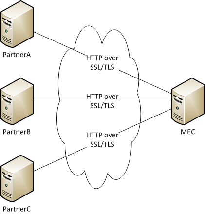
The desired goal is to allow partners to securely send messages to MEC using HTTP over SSL/TLS over the Internet. Also, the idea is to design the architecture in such a way that adding new partners is easy.
Here is the simplified diagram:

Problem
Unfortunately, MEC does not provide incoming channels for HTTPS, there are no HTTPSIn or HTTPSSyncIn channels. There is a WebServiceSyncIn channel that uses WS-Security for XML over SOAP, but it is not what I am interested in. Ideally, I would prefer to use the Infor Grid which already communicates via HTTPS, but unfortunately it does not have a native connection handler for MEC. Surprisingly, most projects I have seen use FTP + PGP, but that is insecure because the FTP username and password transit in clear text, so even though the files are encrypted a man-in-the-middle could intercept the credentials and create havoc like delete files or fill the disk with junk.
| Alternatively, I could develop my own HTTPS server in Java on top of a custom MEC channel; the Java Secure Socket Extension (JSSE) is a good reference guide for how to implement SSL/TLS in Java. I have two options. I could use SSLServerSocket, but it uses blocking I/O contrary to MEC that uses non-blocking I/O for scalability and performance, consequently I would have to forgo scalability and performance. Or I could use SSLEngine to have non-blocking I/O for scalability and performance, but I would have to implement the entire TLS state machine which is overkill for my needs. |
Design
I will setup a public web server https∶//partners.example.com/ at my sample company.
For that, I will setup a reverse proxy with SSL termination upstream of HTTPIn or HTTPSyncIn channels. Thanks to Rickard Eklind for the tip on using Apache + mod_proxy; I will use nginx + ngx_http_proxy_module instead, as it uses non-blocking I/O similar to HTTPIn and HTTPSyncIn, and I think it is easier to setup; either combination will work. I will need to setup the proxy server on the DMZ, setup DNS records, and generate digital certificates.
| If you cannot host your own server on the DMZ, or if you cannot create your own domain name partners.example.com in the DNS records, or if you cannot create your own digital certificate signed by a trusted certificate authority, you may be able to piggy back on an existing public web server in your company and simply add a new virtual directory, like https∶//www.example.com/partners/ that will forward requests to a content-based filtering router, decrypt, filter, re-encrypt and send the requests to your reverse proxy in the LAN. |
| Alternatively, I could have setup a dedicated secure line per partner – such as a VPN with a filter to restrict access to only a specific destination IP address and port number for MEC on the LAN – but for each new partner that would require a lot of paperwork, security clearance, and setup on both ends, which is possible, it is more sandboxed thus more desirable, but it may not be possible in some companies. And in some clouds it may be easier to setup web servers than VPNs. |
Reverse proxy with SSL termination
A reverse proxy is an intermediate server that executes the client’s request to the destination server on behalf of the client without the client being aware of the presence of the proxy; this is unlike a forward proxy that we setup in a browser. In our case, MEC partners will connect to the reverse proxy as if it were MEC, and the proxy will make the requests to MEC.
SSL termination is where the SSL/TLS connection ends. In our case, the partner will initiate the connection to the reverse proxy using the proxy’s digital certificate (which is the proxy’s public key signed by a certificate authority), then the proxy will decrypt the SSL/TLS data using its private key, then the proxy will make the HTTP request in plain text to MEC, and the response will transit back in the opposite direction. The partner will need to previously have verified and added in its keystore the proxy’s certificate or one of the certificate authorities up the chain.
Here is the simplified nginx.conf:
http {
   server {
      server_name partners.example.com;
      listen 443 ssl;
      ssl_certificate cert;
      ssl_certificate_key key;
      location / {
         proxy_pass http://ecollaborator:8080/;
      }
   }
}
Here is the simplified diagram:

| Note 1: This scenario assumes the servers are on the same network which is not true for the Internet. I will put the proxy in the DMZ. See the DMZ section below. |
| Note 2: This scenario assumes the data does not need to be encrypted on the second network segment which is not true either. I will install a second proxy on the same host as MEC. See the end-to-end encryption section below. |
Multiplexing
I need to accommodate multiple partners, for example partnerA, partnerB, and partnerC.
I will use virtual hosting to economically share resources on a single server instead of having a dedicated physical server or virtual private server per partner.
Path-based
I will multiplex by URL path, for example /A, /B, and /C. I conjecture this is no less secure than doing it name-based or port-based. Also, I conjecture it is not subject to XSS attacks so long as we enforce client authentication (see the client authentication section below).
Here is the simplified nginx.conf:
location /A {
   # partnerA
}
location /B {
   # partnerB
}
location /C {
   # partnerC
}
Here is the simplified diagram:

Name-based
Alternatively, I could multiplex by domain name, for example partnerA.example.com, partnerB.example.com, and partnerC.example.com. But then for each new partner I would need a new network interface with a new public IP address – which is scarce to obtain – and update the A records of my DNS server. Or to share the same IP address I could use Server Name Indication (SNI) and update the CNAME records of my DNS server. In any case, I would have to issue a new digital certificate with an updated Subject Alternative Name (SAN) extension, or I could use one wildcard certificate but loose the possibility of Extended Validation Certificate, and anyway wildcard certificate is not considered secure per RFC6125#section-7.2. In the end, it is a maintenance nightmare, and relying on the respective teams could be a bottleneck in some companies.
Port-based
As another alternative, I could multiplex by port number, for example partner.example.com:81, partner.example.com:82, and partner.example.com:83, indeed the same digital certificate will work for any port number, but then for each new partner I would have to update the firewall rules, it is possible, but it is more maintenance, and relying on the respective teams could be a bottleneck in some companies. |
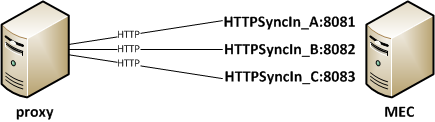
De-multiplexing
Then, I need to de-multiplex the requests to tell the partners apart in MEC. I will setup as many HTTPIn or HTTPSyncIn channels in MEC as there are partners, for example HTTPSyncIn_A on port 8081, HTTPSyncIn_B on port 8082, and HTTPSyncIn_C on port 8083, and in nginx for each partner I will setup a location block with a proxy_pass directive.
Here is the simplified nginx.conf:
location /A {
   proxy_pass http://ecollaborator:8081/;
}
location /B {
   proxy_pass http://ecollaborator:8082/;
}
location /C {
   proxy_pass http://ecollaborator:8083/;
}
Here is the simplified diagram:

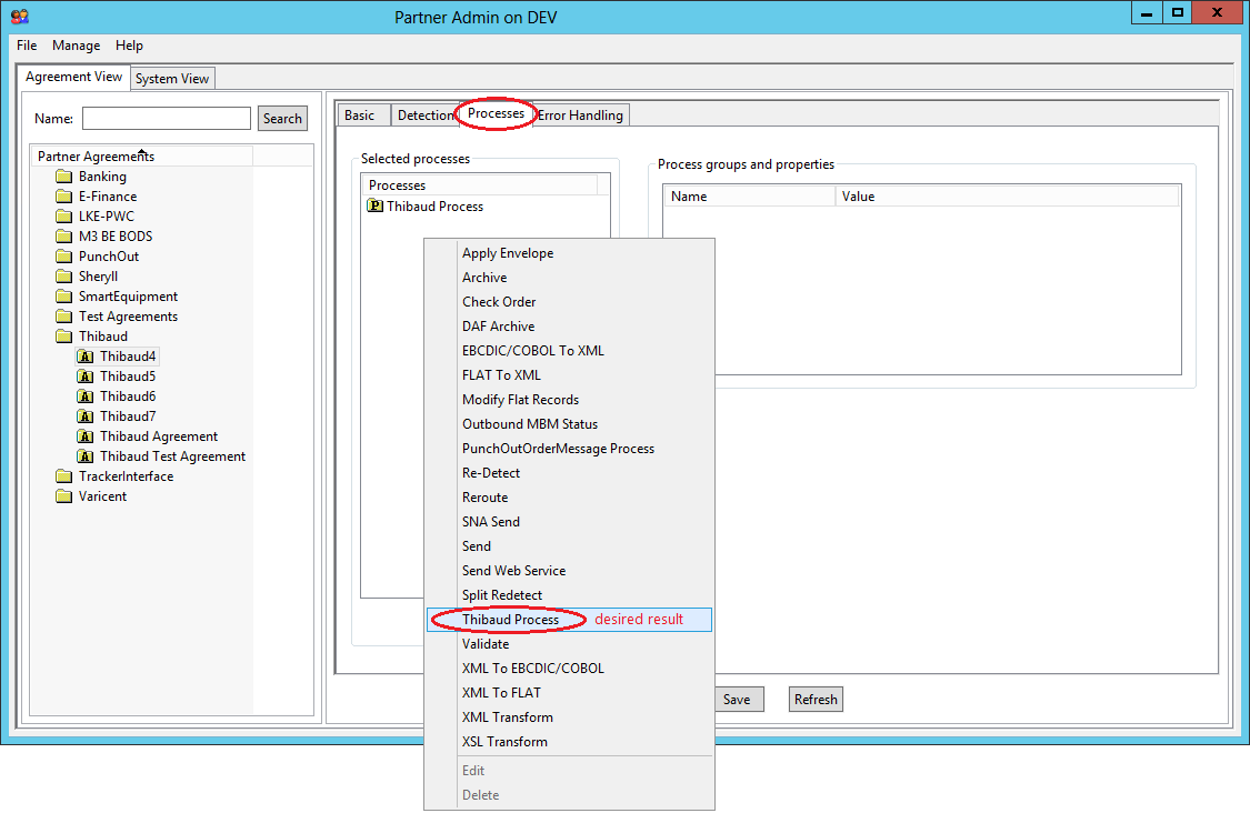
Here are the receive channels in Partner Admin:

Authentication
I need the client to authenticate the server, and vice versa, I need the server to authentication the client.
One of the properties of SSL/TLS is authentication, using digital certificates to affirm the identity of the entities, where server authentication is mandatory, and client authentication is optional. In my case, client authentication is mandatory.
Server authentication
The server (the reverse proxy) will present its digital certificate to the client (the MEC partner), and the client will do its certificate validation to authenticate the server.
Client authentication
On the other hand, the server (ultimately it is MEC) needs to authenticate the client (the MEC partner).
I could setup peer authentication for the proxy to verify the client’s digital certificate, but I have not tested this.
Instead, I will setup HTTP Basic authentication per path in the proxy. The username and password will be encrypted over SSL/TLS so they will remain confidential. I will separate the locations and I will forward to each respective HTTPSyncIn channel in MEC.
Here is the simplified nginx.conf:
location /A {
   auth_basic "A";
   auth_basic_user_file A.htpasswd;
   proxy_pass http://ecollaborator:8081/;
}
location /B {
   auth_basic "B";
   auth_basic_user_file B.htpasswd;
   proxy_pass http://ecollaborator:8082/;
}
location /C {
   auth_basic "C";
   auth_basic_user_file C.htpasswd;
   proxy_pass http://ecollaborator:8083/;
}
In addition to that, we could setup rules in the firewall to only allow the source IP addresses of the partners to access the reverse proxy, it is great if combined with Basic authentication, but insufficient on its own.
| To setup peer authentication, I would use ssl_verify_client. According to the nginx documentation, the context for the ssl_client_certificate directive is http and server only, not location. So I would have to append the various client certificates into one file; to be verified. And then I could use the $ssl_client_cert variable to tell partners apart; to be tested. |
| As another alternative, we could setup client authentication in the MEC agreement using a flat file detector to detect a username and password defined in the HTTP request payload. But that has many problems: 1) It would require hard-coding the username and password in clear text in MEC (passwords should be hashed and salted or at least encrypted), 2) if we need to change the password we would have to change and re-deploy the agreement, and 3) it would put the burden of password verification on MEC which is not designed to thwart brute force attacks. |
Channel detection
Now, we have to carry over the authentication to MEC because even though nginx can pass the Basic authentication header to MEC, MEC does not use it, and if we do not authenticate partners and tell them apart they risk crossing each other. For that I will use a Channel detector in the MEC agreement of each partner.
Here are the channel detectors in Partner Admin:

A drawback emerges from this setup: the number of possible messages per channel is now limited to only one. If partner A wants to send two different messages 1 and 2, for example new customer order and new rental agreement, MEC is not able to process two messages in one agreement, and it cannot reuse the same receive channel in another agreement. To assist MEC, I would have to discriminate further by path in nginx, for instance /A/message1, and /A/message2, and have as many receive channels as possible messages. I can use nested location blocks (I have not tested this). Here is the simplified nginx.conf:
location /A {
   auth_basic "A";
   auth_basic_user_file A.htpasswd;
   location /message1 {
      proxy_pass http://ecollaborator:8001/;
   }
   location /message2 {
      proxy_pass http://ecollaborator:8002/;
   }
}
I am not trained in MEC Partner Admin so maybe there is a way around it. |
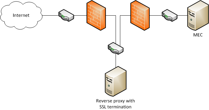
…on the Internet
Once a web server is placed on the Internet it will get attacked, so consult with your network and security team to harden your servers. It should at least be in the DMZ between one or two firewalls:
Here is a simplified diagram:

Take also into account: high availability, redundancy, fail over, disaster recovery, edge caching, DNS round robin, IDS, content-based firewall, restrict physical access to the servers, restrict permissions to the files, software updates, operating system support, etc.
| Note: The HTTP channels in MEC will be the single point of failure in spite of all this setup. The MEC Server runs on the Infor Grid, and the Infor Grid is meant to be distributed, fault tolerant, load balanced, scalable, and redundant. However, the HTTP channels of MEC are not Grid enabled (the HTTPIn and HTTPSyncIn channels manage their port and HTTP server themselves), so they are not distributed, fault tolerant, load balanced, scalable, and redundant, they are a single point of failure. You can learn more about Infor Grid application development on my other post. |
End-to-end encryption
Now we need end-to-end encryption to protect the data on the second network segment from the reverse proxy on the DMZ to MEC on the LAN. For that, I will chain two reverse proxies with SSL termination. I will simply install the second proxy on the same host as MEC. And I will issue a second pair of digital certificate and private key for the second proxy that the two proxies will use to encrypt/decrypt. That simplifies the rules of the internal firewall, and I can setup peer authentication between the proxies.
Here is the simplified diagram with the two proxies X and Y:

How to add new partners
To add a new partner D:
- Setup a new Receive channel in Partner Admin with a new HTTPIn or HTTPSyncIn channel for example on port 8084
- Setup a new agreement with channel detector
- Test by making an HTTP request to MEC on port 8084
- Setup the inner proxy:
- Setup a new location block in nginx.conf for path /D with proxy_pass directive to port 8084 and basic authentication
- Setup a new htpasswd file
- Restart nginx
- Test by making an HTTPS request to the proxy
- Setup the outer proxy to pass requests to the inner proxy and test it (I do not have guidelines here as my actual setup for the outer proxy uses a content-based router, not nginx)
- Test by making an HTTPS request from the partner to https∶//partners.example.com/D
How to setup multiple environments
To setup multiple environments, such as DEV, TST, PRD, use nested location blocks in nginx.conf, for example /DEV, /TST, /PRD (I have not tested this).
Here is the simplified nginx.conf:
location /DEV {
   location /A {
      # Development partnerA
   }
   location /B {
      # Development partnerB
   }
}
location /TST {
   location /A {
      # Test partnerA
   }
   location /B {
      # Test partnerB
   }
}
Limitations
This is the first time I setup this architecture, I have not tested all the design variations, and I have not validated that my design is a good design nor that it is secure. I am currently using a similar architecture at a major customer of mine for their production environment where they have multiple data centers, high availability, redundancy, fail over, and disaster recovery. One of their technical people reviewed the solution, they approved it, and the only concerns were that this solution might be over engineered (plausible) and that the MEC channels are the single point of failure anyway (true). I conjecture the solution is good enough and secure enough for our needs. Of course I could be completely wrong and not see a major flaw. Nothing is fully secure anyway. Please let me know what you think in the comments below.
Upcoming version of MEC
Johan Löfgren, the component owner for MEC at Infor Product Development, said they are working on a native HTTPSIn channel for an upcoming version of MEC; it is not GA and the release may or may not occur. If and when that happens, you would not need to chain two proxies anymore, you would just keep one proxy in the DMZ and use proxy_pass to send the requests directly to the HTTPSIn channels in MEC.
UPDATE 2015-04-12: What is being released is SFTP, no plans for HTTPS at the moment.
Conclusion
This was one solution to setup incoming HTTP channels in MEC to securely receive messages over SSL/TLS over the Internet. MEC does not have an HTTPSIn or HTTPSSyncIn channel, and I did not want to implement my own HTTP server over SSL/TLS in Java. Instead, I chose to setup a reverse proxy with SSL termination in a DMZ, with digital certificate and private keys, with HTTP basic authentication, with a second proxy in the MEC host for end-to-end encryption. This solution has many properties: it uses standard HTTP and SSL/TLS, and it is easy to add new partners. Also, we simplified the architecture upstream such that we do not have to rely on other teams if we need to add a new partner, which can be a maintenance nightmare and bottleneck in some companies; we can simply add new partners downstream in our proxy and Partner Admin. I conjecture this solution is secure for our needs. But remember it has not been fully reviewed, and the MEC channels are the single point of failure.
Please let me know what you think in the comments below.
Related articles
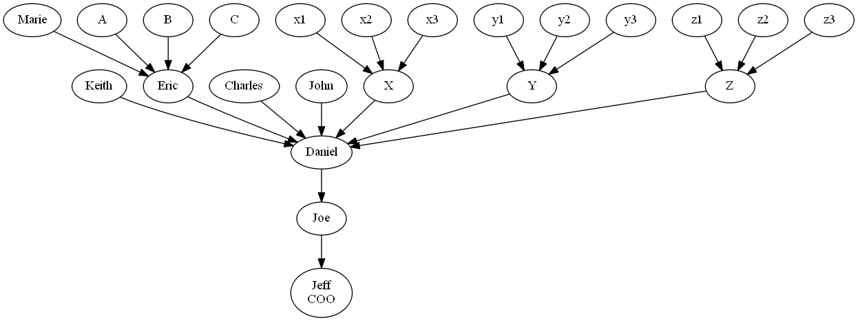
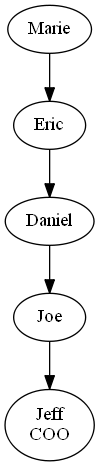
 Approval flows get complex quickly, with many decisions to take, many levels of approval to have, many design trade-offs to consider, and all sorts of scenarios to support.